
What Is the Vacuum Brazing Process and How Does It Work?
The Vacuum Brazing Process joins metal components by heating them with a filler alloy inside a vacuum furnace. Unlike welding, it melts the filler, not the base materials. The liquid filler flows into a close-fitting joint through capillary action, then solidifies as the assembly cools. Small details matter.
A typical cycle begins with clean parts, carefully positioned with the filler alloy. After loading, the furnace removes much of the air and follows a controlled heating schedule. As the temperature rises, the filler melts and spreads along the joint surfaces. Cooling then forms the bond. Flux is usually unnecessary, though suitable materials and clean surfaces remain essential. That sounds simple.
The outcome depends on more than furnace temperature. Joint clearance, alloy choice, part geometry, and heating uniformity all affect how the filler flows. In practice, the process can be less forgiving than a neat diagram suggests: small gaps or uneven heating may produce incomplete joints. Vacuum level and cycle settings also vary with the materials and equipment, so established procedures and inspection matter. This overview explains how each stage works, what influences joint quality, and where careful process control makes a practical difference.
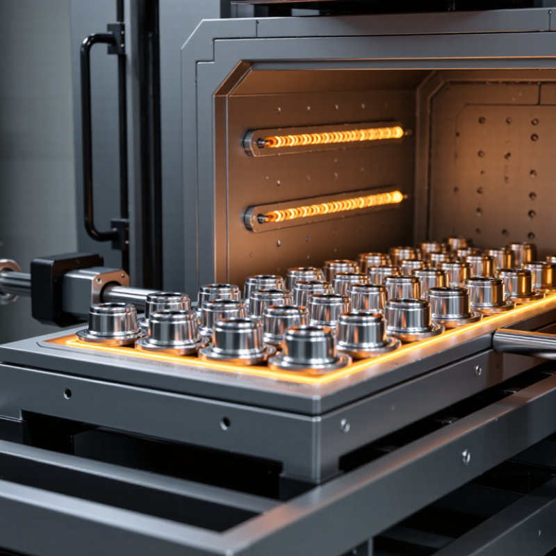
Vacuum Brazing Fundamentals: Filler Metals Melt Above 450°C
Vacuum brazing joins closely fitted metal parts by heating them in a low-pressure furnace. The filler metal melts and flows into the narrow joint, while the base metals remain solid. The key threshold is 450°C. The American Welding Society’s A3.0M/A3.0 terminology standard defines brazing by a filler metal liquidus above this temperature. That boundary matters.
The actual cycle depends on the filler alloy and the parts being joined. Operators heat the assembly until the filler melts, wets the surfaces, and fills the joint by capillary action. A vacuum helps limit oxidation, which can otherwise obstruct flow and weaken bonding. ASM Handbook, Volume 6A, describes vacuum brazing as a process suited to clean, flux-free joints in controlled furnace conditions. But 450°C is not a furnace setting. It is a classification threshold, and treating it like a recipe would be a mistake.
For example, a thin stainless-steel assembly may need a carefully controlled ramp to avoid distortion, while thicker parts heat more slowly. Joint clearance matters too: an overly wide gap can interrupt filler flow. The AWS threshold gives engineers a shared definition; it does not guarantee a sound joint. That part takes testing.
What Is the Vacuum Brazing Process and How Does It Work? - Vacuum Brazing Fundamentals: Filler Metals Melt Above 450°C
| Process Dimension | What Happens | Typical Details and Considerations |
|---|---|---|
| Brazing principle | A filler metal melts and flows into a closely fitted joint while the base components remain solid. | In the commonly used definition, brazing filler metal has a liquidus temperature above 450°C (840°F). Capillary action helps draw the molten filler through the joint clearance. |
| Joint preparation | Parts are cleaned, aligned, and assembled with filler metal placed at or near the joint. | Oil, dirt, and excessive oxide can prevent wetting. Joint clearance must suit the materials, filler, and process temperature; there is no single clearance suitable for every design. |
| Vacuum environment | The loaded assembly is heated in a sealed furnace as air and other gases are removed. | Vacuum level is selected for the materials and process requirements. Industrial furnace operating pressures can vary widely; approximately 10−2 to 10−5 mbar is an illustrative range, not a universal specification. |
| Heating and outgassing | The furnace heats the parts in controlled stages, allowing trapped gases and volatile residues to be removed before brazing. | Heating schedules depend on part mass, geometry, materials, and furnace loading. Thorough cleaning helps reduce contamination and outgassing. |
| Brazing temperature | The assembly is brought above the filler metal’s liquidus temperature so the filler can melt and wet the joint surfaces. | The required temperature is determined by the selected filler and base materials. Many vacuum-brazing cycles fall roughly between 600°C and 1200°C, but some applications are outside this range. |
| Filler flow and joint formation | Molten filler wets compatible surfaces and is drawn into the joint by capillary action, then forms a bond as it solidifies. | Good results depend on surface condition, joint fit, filler compatibility, and a suitable time at temperature. The base metals are not intended to melt. |
| Filler metal selection | The filler is chosen to suit the base metals, service environment, joint design, and furnace cycle. | Common filler families include silver-, copper-, nickel-, and gold-based alloys. Their melting ranges and suitability differ; the filler must not damage or excessively interact with the base materials. |
| Cooling | After the brazing hold, the assembly is cooled under a controlled atmosphere or vacuum according to the process specification. | Cooling rate can affect distortion, residual stress, and the properties of heat-treated materials. Some furnaces use gas cooling when the load and equipment permit. |
| Typical advantages | The process can produce clean joints without routine flux use and can braze multiple joints in one furnace cycle. | Vacuum processing can limit oxidation and reduce post-braze flux removal. Outcomes depend on material chemistry, surface preparation, furnace condition, and process control. |
| Quality checks | Completed assemblies are inspected to confirm joint integrity and dimensional requirements. | Depending on the application, checks may include visual inspection, dimensional measurement, leak testing, or appropriate non-destructive testing. |
Values shown are general guidance only. Actual temperatures, vacuum levels, clearances, and cycle times should be established for the specific materials, component design, and applicable process specification.