
Industrial plants rely on dependable filtration to protect equipment, maintain product quality, and keep processes moving. Yet choosing among Filter Units is rarely a simple matter of comparing catalog ratings. A system handling warm, viscous process water may need a different design from one capturing fine dust in a dry production area. The operating details matter.
This guide examines common industrial options, including cartridge, bag, and self-cleaning units, and explains where each may fit. It also considers flow rate, pressure drop, contaminant size, media compatibility, and cleaning requirements. These factors affect performance and maintenance, but no single specification tells the whole story. Small details matter.
In real facilities, readings can shift as filters load, production changes, or cleaning intervals prove longer than expected. An initial estimate may need revision. That is worth acknowledging, not hiding. Comparing units against actual process conditions, manufacturer documentation, and routine service needs gives engineers and buyers a more reliable starting point. The goal is not to name one universal winner, but to identify practical choices and the questions that help narrow them down.
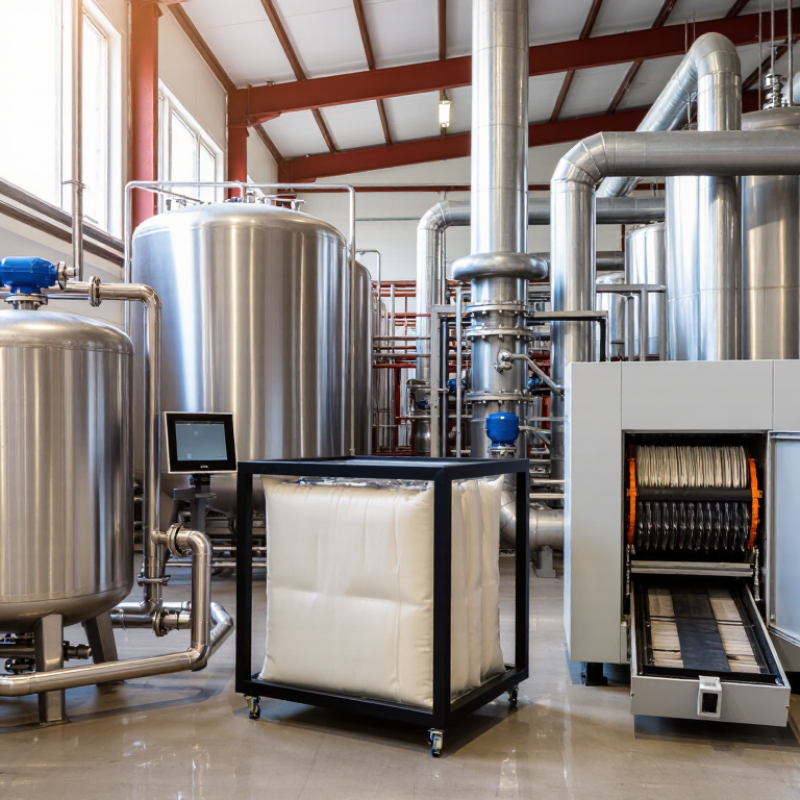
An industrial filter unit removes unwanted material from air, liquid, or process gas before it reaches equipment or leaves a work area. It may use a replaceable cartridge, a bag, a screen, or a porous membrane. The right choice depends on the fluid, particle size, temperature, and flow rate. No single unit handles every job well.
In a dust-collection line, a filter captures particles as air passes through its media. The cleaned air then returns to the room or moves downstream, depending on system design. In a coolant circuit, a liquid filter can trap chips and grit before they damage pumps or affect a finished surface. It is a barrier, not a cure-all. Very small particles may pass through, while sticky or wet dust can clog media quickly.
Operators often monitor differential pressure, flow, and the material collected. Rising pressure can signal a loaded filter, but readings should be compared with the unit’s normal operating range. That detail matters. A filter that looks clean outside may be blocked inside. Maintenance schedules help, though service needs vary with production and contamination. On paper, selecting a unit seems simple. In a working plant, it rarely is.
Top Filter Units for Industrial Applications
Industrial filter units capture contaminants by directing process air through a collection surface. Larger particles strike fibers or settle as airflow changes direction; finer particles are intercepted or move randomly until they contact the media. In many dust collectors, accumulated dust forms a surface layer that improves capture. It also raises resistance to airflow. Small details matter.
The U.S. Environmental Protection Agency reports that fabric-filter systems can achieve particulate collection efficiencies of 99–99.9%, depending on design and operating conditions. That figure is not a promise for every installation. Poor seals, damaged media, or unsuitable airflow can reduce real-world performance. A filter may appear intact while dust escapes through a small leak.
For finer particles, filter ratings offer useful—but limited—guidance. Under ASHRAE Standard 52.2, MERV 13 filters meet minimum efficiencies of 50% for particles from 0.3–1 micrometers, 85% from 1–3 micrometers, and 90% from 3–10 micrometers. These laboratory ratings do not predict performance in every industrial process. Operators should compare particle size, temperature, moisture, and pressure-drop readings with the unit’s specifications. Regular inspection helps reveal uneven loading before it becomes a production problem.
Minimum particle removal efficiencies for selected MERV ratings, tested under ASHRAE Standard 52.2. The particle-size bands are 0.3–1, 1–3, and 3–10 micrometres. Higher ratings indicate greater removal in these ranges; actual results depend on airflow, installation, and operating conditions.
Baghouse units suit dusty processes such as cement handling, grain transfer, and metalworking. Their fabric bags trap particles as air passes through. The U.S. EPA’s Fabric Filter fact sheet reports typical collection efficiencies of 99–99.9%, though actual results depend on dust, media, and maintenance. Cartridge units work well where floor space is tight and fine dust loads are moderate. For liquids, basket strainers catch larger debris in pipelines, while cartridge filters help protect pumps and downstream equipment. Compressed-air coalescing filters remove oil aerosols and water droplets before they reach sensitive tools.
Real plants vary. A filter that performs well on paper may clog quickly when dust is sticky or humidity changes. Check differential pressure, not just the calendar. The U.S. Department of Energy’s Improving Compressed Air System Performance sourcebook notes that raising compressor discharge pressure by 2 psi can increase energy use by about 1%. A loaded filter can contribute to that pressure loss.
Tips: Match filter media to particle size, temperature, and chemical exposure. Record pressure drop at installation, then compare readings during routine inspections. Drain liquid bowls and inspect seals; small leaks are easy to miss. Keep one spare element on hand, but verify its specification before fitting it.
Selecting a filter unit starts with understanding what the process actually needs to remove. Identify the contaminant type, particle size, and expected concentration. A clear liquid may still carry fine solids that quickly block an undersized element. Measure the real load. Record flow rate, operating temperature, pressure, and any changes between shifts. These details help determine whether a basket strainer, bag unit, or cartridge housing is suitable. Check that wetted materials tolerate the process fluid, including cleaning chemicals. Small details matter.
Next, balance filtration performance with pressure drop and maintenance demands. A finer element may improve product quality but require more frequent replacement. Confirm the unit can handle peak flow, not only the average shown on a process sheet. Leave room to open the housing and remove loaded elements safely. Differential-pressure readings can signal when service is needed, while samples taken before and after filtration help verify performance. If conditions vary, a short trial under real operating loads can reveal issues that calculations miss. That is not failure. It is useful evidence. Initial sizing may still need adjustment after operators see how quickly the filter loads.
| Filter Unit | Typical Separation Range | Suitable Process Fluids | Key Strengths | Selection Considerations | Common Industrial Uses |
|---|---|---|---|---|---|
| Basket or Y-Strainer | Coarse screening, typically about 100–3,000 µm, depending on screen or perforation | Water, oils, process liquids, and some gases | Simple, robust protection for pumps, valves, and downstream equipment; screens can often be cleaned and reused | Best for larger debris, not fine-particle removal. Check screen open area, pressure drop, and cleaning access. | Pipeline protection, cooling-water lines, pump inlets, and utility services |
| Bag Filter Housing | Common bag ratings range from about 1–800 µm; ratings may be nominal or absolute | Low- to moderate-viscosity liquids | Handles relatively high solids loading and offers quick bag changes; available in single- and multi-bag configurations | Confirm micron-rating definition, liquid viscosity, solids load, bag compatibility, and the required changeout differential pressure. | Paints and coatings, chemicals, water treatment, food-process liquids, and industrial oils |
| Liquid Cartridge Filter | Commonly about 0.5–100 µm, with media and construction determining the rating | Water, solvents, chemicals, and other compatible liquids | Compact design with a broad choice of depth, pleated, and membrane media; suitable for polishing and finer particle control | Check flow capacity, viscosity, compatibility, dirt-holding capacity, and whether the application requires a nominal or absolute rating. | Final liquid polishing, chemical processing, electronics water, and pre-filtration |
| Self-Cleaning Screen Filter | Often about 20–3,000 µm, depending on screen design and cleaning method | Water and compatible low-viscosity process liquids | Automatic or semi-automatic cleaning can reduce routine element replacement and limit process interruption | Requires suitable solids characteristics and cleaning conditions. Verify minimum operating pressure, backwash flow, and waste handling. | Intake water, cooling circuits, irrigation systems, and continuous-flow process lines |
| Coalescing Filter | Designed to remove dispersed liquid droplets or aerosols; performance depends on droplet size, flow, and media | Compressed air, natural gas, and other compatible gas streams | Combines small droplets into larger drops that can drain from the vessel; can reduce liquid carryover | Specify the target liquid, flow conditions, allowable pressure drop, drainage arrangement, and required downstream dryness. | Compressed-air systems, gas conditioning, instrument air, and protection of downstream equipment |
| Particulate Air Filter | Available in a wide range, from coarse dust collection to high-efficiency grades; performance should be specified by test standard and particle size | Air and compatible process gases | Captures airborne solids using fibrous, pleated, or depth media; grade selection can be matched to process cleanliness needs | Consider dust loading, humidity, temperature, airflow, sealing, and the pressure-drop limit. Efficiency figures are not comparable unless tested under the same standard. | Ventilation, dust control, process-air supply, and equipment protection |
| HEPA Filter Module | High-efficiency particulate filtration; a common HEPA benchmark is at least 99.97% efficiency at 0.3 µm under the applicable test method | Clean air and compatible, non-corrosive gas streams | Provides high particle removal when correctly installed and leak-tested | Higher pressure drop and careful sealing are important considerations. Select by the relevant regional standard and required system airflow. | Cleanrooms, pharmaceutical areas, laboratories, and critical process enclosures |
| Activated Carbon Adsorber | Removes selected vapors and odors by adsorption; it is not a general-purpose particle filter | Air or gas streams containing compounds compatible with the selected carbon | Can reduce certain volatile organic compounds, odors, and trace contaminants | Performance depends on contaminant type and concentration, humidity, contact time, and carbon capacity. Plan for monitoring and media replacement. | Odor control, solvent vapor treatment, and gas-stream polishing |
| Magnetic Separator | Targets ferrous and some magnetically responsive particles; capture depends on particle size, magnetic properties, and field strength | Compatible liquids, slurries, or dry bulk materials, depending on separator design | Can remove ferrous debris without a disposable filter element and help protect process equipment | Does not remove non-magnetic contaminants. Confirm material properties, flow pattern, cleaning method, and required separation level. | Metalworking fluids, mineral processing, plastics, and material handling |
| Selection note: Filtration ratings, efficiency, flow capacity, and pressure drop vary with element design, fluid properties, operating conditions, and test method. Confirm the required contaminant, target cleanliness, compatibility, operating limits, and maintenance plan with the filter specification before selection. | |||||
Industrial filter units work best when installation matches the actual process conditions. Confirm the expected flow, temperature, pressure, and fluid compatibility before positioning the housing. Install it in the orientation specified for the unit, and leave room to remove the cover and change elements. A cramped installation can turn a routine service into a slow, awkward job. Small details matter.
Before commissioning, inspect seals and connections, then start the system gradually. Check for leaks and record the initial differential pressure across the filter. This reading gives operators a useful baseline. During operation, compare later readings under similar flow conditions; a rising pressure difference may indicate loading, but it is not proof by itself. Flow changes, damaged gauges, or a poorly seated element can also distort the picture. One reading can mislead.
Set inspection intervals using the process history, not just a calendar. Look for unusual pressure changes, bypass leakage, corrosion, and changes in the filtered output. When replacing an element, isolate and depressurize the unit according to site procedures, and confirm the replacement fits correctly. Keep dates, readings, and observations together in a service log. It may feel fussy at first, and records are not always complete, but even imperfect notes can reveal a recurring problem before it causes an unplanned shutdown.
By continuing to browse or by clicking “Accept All Cookies,” you agree to the storing of first- and third-party cookies on your device to enhance site navigation, analyze site usage, and assist in our marketing efforts. View our Privacy and Cookie Policy.