A High Torque Brushless Dc Motor can move a demanding load, but the largest torque figure on a product page rarely tells the whole story. The International Energy Agency’s report, Energy-Efficiency Policy Opportunities for Electric Motor-Driven Systems, estimates that electric motor-driven systems use about 45% of global electricity. That figure reflects a broad range of equipment, not brushless DC motors alone. Still, it shows why choosing the right motor and drive matters for energy use and reliable operation.
Start with the load. A conveyor moving heavy cartons, for example, may need strong starting torque, steady speed, and repeated starts throughout a shift. Check continuous and peak torque separately, then compare them with the motor’s speed range, voltage, current, and duty cycle. Heat matters. So does the controller: poor matching can limit performance even when the motor appears powerful on paper. Consider the available space, mounting method, ambient temperature, and expected service life, too.
Specifications can mislead. Peak torque is not a promise of continuous output. A motor that works well on a test bench may struggle inside a warm, enclosed machine. This guide explains how to compare motor ratings, assess the load, and verify motor-driver compatibility before choosing a model. The right choice depends on the full operating profile, not one impressive number. An honest review of your assumptions can prevent an expensive mismatch.
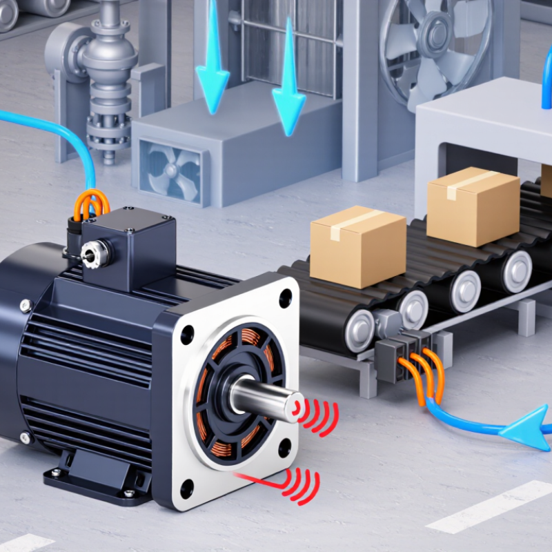
Choosing a high-torque brushless DC motor starts with the real load, not a catalog’s peak-torque figure. Record shaft speed and torque during startup, steady running, and any jam or incline condition. The IEA’s 2011 report, Energy-Efficiency Policy Opportunities for Electric Motor-Driven Systems, estimates that motor-driven systems use about 45% of global electricity. That scale makes accurate sizing worthwhile. Measure it under load.
Separate continuous torque from short bursts. A conveyor may need a brief surge to start a full belt, then much less torque to keep it moving. Check the motor’s torque-speed curve at your actual supply voltage; torque generally falls as speed rises. Include acceleration: rotating inertia adds demand beyond the steady load. A guessed value is tempting, but it is not a measurement.
Duty cycle determines whether heat can escape between runs. IEC 60034-1 defines duty types, including S1 continuous duty and S3 intermittent periodic duty. Log each run’s duration, rest period, and starts per hour, then compare that pattern with the motor and drive’s thermal limits. A hot enclosure or frequent starts can change the choice. Heat changes everything. I would keep early estimates provisional, especially when friction or payload varies.
A high-torque BLDC motor is not defined by one impressive number. Check whether the stated torque is continuous or peak. Continuous torque is the useful figure for a load that runs for hours; peak torque usually applies only briefly. Numbers can mislead. Ask for the torque-speed curve, since available torque often falls as speed rises. A motor that starts a heavy conveyor may not maintain the same force at full speed.
Compare torque constant, rated current, and supply voltage together. The torque constant estimates how much torque the motor produces per ampere, while current limits affect what it can deliver in practice. Check the specified operating conditions, too. A rating measured with strong cooling may not hold inside a sealed enclosure. Heat matters. Winding temperature and ambient temperature can reduce continuous output, especially during frequent starts.
Match shaft speed and torque to the actual mechanism, including gears, belts, and load inertia. A gearbox can increase output torque, but it also changes speed and adds losses. Review duty cycle, mounting space, shaft dimensions, and feedback requirements before choosing. If the datasheet leaves these details vague, request test conditions or a measured curve. I would not select a motor from peak torque alone; that shortcut is tempting, but it can lead to a motor that runs hot or stalls under real load.
Compare continuous and peak torque across representative BLDC motor size classes. These illustrative values show typical scaling, not guaranteed specifications for any particular motor.
Selection tip: Size the motor for the continuous torque required at your operating speed. Treat peak torque as a short-duration capability, and verify its permitted duration, current limit, cooling conditions, and torque-speed curve in the motor datasheet.
Start with the load, not the motor’s advertised peak torque. Measure the torque required at the shaft during normal operation, then note the highest demand during startup or acceleration. Measure the load. A conveyor carrying a full bin may need much more starting torque than it needs once moving. Record the required speed at the same shaft point; torque and speed must describe one operating condition, not two unrelated numbers.
Compare that operating point with the motor’s torque-speed curve at the intended voltage. Check continuous torque for sustained work and peak torque for brief demands. Peak ratings are not a safe substitute for continuous ratings. That matters. A motor running near its limit can heat up, lose efficiency, or trigger a controller’s current limit. Include duty cycle, ambient temperature, and how often the load starts and stops.
If a gearbox is involved, calculate the output speed and torque after the ratio and account for losses. Leave margin. Too little margin can cause sluggish starts, while excessive oversizing may add cost and make control less precise. I would verify the selection with a loaded test: measure current, case temperature, and startup time over several cycles. The first estimate may be wrong; real friction and changing loads often reveal details the calculation missed.
How to Choose a High Torque Brushless DC Motor
Check Electrical, Mechanical, and Controller Compatibility
High torque alone does not guarantee a suitable motor. Match its rated voltage to the supply, then check peak current against battery, wiring, and controller limits. A motor may draw much more current during acceleration or a jam. The IEA’s Energy-Efficiency Policy Opportunities for Electric Motor-Driven Systems reports that motor systems use about 45% of global electricity. That figure covers many motor types, but it underlines why correct system matching matters.
Compare the torque-speed curve with the actual load, not just the advertised peak torque. Check shaft diameter, keyway, mounting pattern, and available space; a few millimeters can derail an otherwise sound fit. Also consider load inertia and cooling. A motor producing high torque at low speed may overheat if ventilation is poor. Small details matter. I would recheck the duty cycle, since real machines rarely run at one steady load.
The controller must support the motor’s voltage, continuous and peak current, and commutation method. Confirm whether Hall sensors are required and whether the controller accepts their signal pattern. For braking or overhauling loads, check regenerative-current handling and braking strategy. The U.S. Department of Energy’s Improving Motor and Drive System Performance guide notes that motor-driven systems account for roughly 68% of U.S. manufacturing electricity use. It is not a BLDC-specific statistic, yet it reinforces the value of evaluating the motor, controller, and load as one system. A small mismatch can become heat, noise, or lost torque.
A high-torque brushless DC motor should be compared under the conditions it will actually face. At low speeds, producing strong torque can require substantial current, and current creates heat in the windings. Check the motor’s continuous torque and temperature limits, not just its peak rating. Peak torque may be available only briefly. Heat accumulates quickly.
Thermal limits depend on more than the motor housing. Ambient temperature, airflow, mounting, and the controller’s current settings all affect winding temperature. A motor rated for a cool, ventilated test bench may behave differently inside a compact machine. Compare temperature-rise data at similar loads and duty cycles. If test conditions are missing, treat the figures cautiously; I would not assume two ratings are directly comparable.
Efficiency also varies with speed and torque, so a single peak-efficiency number can mislead. Look for a performance map and identify the operating range your equipment uses most. Lower losses can reduce heat, but they do not guarantee long service life. Bearings, insulation, vibration, contamination, and repeated overloads matter too. A useful comparison asks how the motor performs after sustained operation, not only during a short demonstration. It is easy to overlook that distinction.
| Comparison factor | Compact, high-speed motor | General-purpose motor | Low-speed, high-torque motor |
|---|---|---|---|
| Typical application | Fans, spindles, and compact machinery | Automation axes, pumps, and conveyors | Direct-drive wheels, turntables, and heavy-duty actuators |
| Example DC bus voltage | 24–48 V | 48–96 V | 48–96 V |
| Example continuous operating point | 3.2 N·m at 3,000 rpm; approximately 1.0 kW mechanical output | 5.0 N·m at 1,500 rpm; approximately 0.79 kW mechanical output | 8.0 N·m at 600 rpm; approximately 0.50 kW mechanical output |
| Illustrative peak torque | 6–9 N·m for short acceleration events | 10–15 N·m for short acceleration events | 16–24 N·m for short acceleration events |
| Typical peak-torque constraint | Use only for short periods; verify the controller’s current limit and the motor’s thermal model. | Peak duration depends on winding temperature, starting temperature, and cooling. | High current can heat the winding quickly at low speed, where shaft-mounted fan cooling may be limited. |
| Indicative motor efficiency near rated load | 85–91% | 88–93% | 85–92% |
| Thermal limit to check | Winding temperature and heat rejection from the compact housing | Continuous winding temperature under the specified ambient and mounting conditions | Winding temperature at low speed and high torque; consider forced cooling if needed |
| Insulation reference | Class F insulation has a 155°C thermal class limit. This is an insulation-system classification, not a recommended normal operating temperature; follow the motor manufacturer’s winding-temperature and temperature-rise limits. | ||
| Cooling and installation factors | Check enclosure airflow, ambient temperature, and mounting heat transfer. | Confirm the rated cooling method and allow adequate clearance around the frame. | Check whether the rating assumes a heat-conductive mount, liquid cooling, or external airflow. |
| Service-life considerations | Bearing life may be reduced by high speed, excessive belt tension, contamination, or poor alignment. | Check bearing load, lubrication, vibration, and operating hours for the intended duty cycle. | Check radial and axial loads carefully; high torque does not itself determine bearing life. |
| Bearing life metric to request | Ask for calculated bearing L10 life at the actual speed, radial and axial loads, lubrication, and operating conditions. L10 is a statistical rating life: 90% of a group of identical bearings are expected to reach or exceed it under the stated conditions. | ||
| Best suited when | Speed and compact size matter more than maximum torque at low rpm. | A balanced speed, torque, efficiency, and thermal profile is required. | High shaft torque at low speed is needed, potentially without a gearbox. |
Selection note: Compare continuous torque at the required speed—not peak torque alone. Confirm the torque–speed curve, controller current limits, ambient-temperature rating, cooling assumptions, winding-temperature limits, and bearing-life calculation before sizing a motor.
By continuing to browse or by clicking “Accept All Cookies,” you agree to the storing of first- and third-party cookies on your device to enhance site navigation, analyze site usage, and assist in our marketing efforts. View our Privacy and Cookie Policy.