
Selecting the right Foot Pedal Valve is not a minor purchasing decision. It affects operator control, cycle consistency, maintenance time, and pneumatic energy use. In a busy workshop, the difference may appear as a firm treadle, a delayed return, or a leaking fitting beside a dusty machine.
The U.S. Department of Energy’s technical report, Improving Compressed Air System Performance, states that leaks can waste 20–30% of compressor output. That figure gives valve selection practical weight. A poorly sealed pedal valve can quietly increase compressor demand. The problem may remain invisible for months. It should not.
Reliability engineer R. Keith Mobley wrote, “Reliability is not a function of how much you spend. It is a function of how you spend it.” His point applies directly here. A premium valve is not automatically the best valve. Port size, operating pressure, exhaust design, pedal guard, return force, mounting style, and replacement-part availability must match the application. ISO 1219 documentation can also help engineers interpret pneumatic symbols and circuit functions consistently.
This guide compares seven industrial Foot Pedal Valve options using those practical criteria. It considers hands-free operation, contamination exposure, response feel, serviceability, and operator safety. Some specifications are easy to compare. Others are not. Manufacturer claims may overlook harsh floors, wet gloves, or repeated side loading. No ranking is perfect. The final choice still depends on the machine, the operator, and the maintenance reality on site.
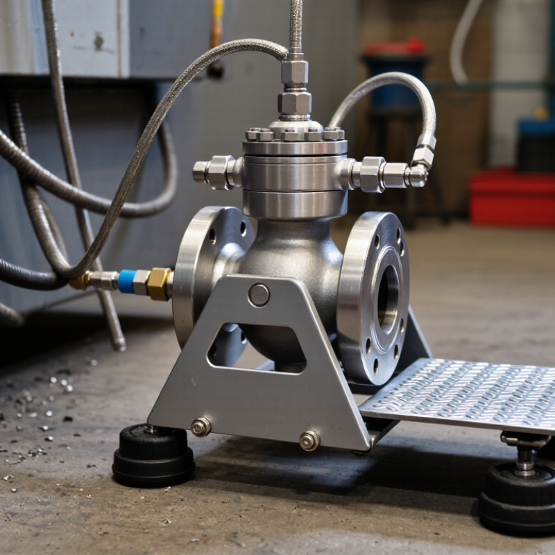
A foot pedal valve is a pneumatic control device operated by the user’s foot. It starts, stops, or redirects compressed air without requiring hand movement.
Inside, a spring-loaded spool or poppet changes the air path when the pedal moves. A three-way valve can pressurize or exhaust one actuator port. A five-way valve can control both directions of a double-acting cylinder. The choice depends on the machine’s movement, pressure, and safety design.
In a typical setup, pressing the pedal sends air to a cylinder. Releasing it may return the spool through spring force, depending on the valve’s configuration. Guards, exhaust silencers, and a locking pedal cover can reduce unintended operation.
ISO 4414 requires pneumatic systems to address safe isolation, stored energy, and controlled exhaust. The U.S. Department of Energy reports that compressed air may consume about 10% of industrial electricity, while leaks can waste 20–30% of compressor output.
That makes correct valve sizing important. A poorly matched valve can cause slow motion, pressure loss, or repeated cycling.
I once assumed a stronger return spring always improved control. It did not. The pedal became tiring, and operators began pressing it from awkward angles.
Practical testing should measure pedal force, response time, leakage, and cylinder behavior under real loads. A clean workshop test is useful, but it can hide dust, oil mist, and vibration found on the production floor.
Key Features of Foot Pedal Valves for Industrial Applications
The seven best foot pedal valves for industrial use should support safe, repeatable control under real production pressure. Start with actuation force. A stiff pedal can cause fatigue during long shifts, while an overly light pedal may trigger accidentally. A guarded treadle, non-slip surface, and positive return spring help operators keep control near conveyors, presses, and assembly fixtures. Short travel also matters, especially when workers wear protective footwear.
Pressure and flow ratings must match the machine circuit, not just the catalog headline. Check port size, exhaust capacity, response time, and compatibility with compressed air or hydraulic media. ISO 4414 stresses risk reduction in pneumatic systems, including unexpected movement and stored energy. That standard does not make a valve safe by itself. Installation still needs isolation, testing, and clear maintenance procedures.
The U.S. Bureau of Labor Statistics reported 888,220 private-industry cases involving days away from work in 2023. Foot controls cannot prevent every injury, but thoughtful placement may reduce awkward hand movements. Choose corrosion-resistant bodies for washdown areas and sealed switches where dust enters easily. IP ratings help, but they are often misunderstood. A higher number does not replace proper guarding. In practice, I would test the pedal with gloves, wet soles, and repeated cycling before approval. Specifications can look perfect. Operators may disagree.
7 Best Foot Pedal Valves for Industrial Use
How to Choose the Right Foot Pedal Valve for Your System
Choosing a foot pedal valve starts with the machine, not the catalog. Confirm whether your system uses pneumatic, hydraulic, or low-pressure air control. Check the working pressure, flow rate, port size, and required actuation force. A valve that feels comfortable on a test bench may become tiring during an eight-hour shift. Measure the operator’s foot position, pedal travel, and available floor space before ordering.
In factory inspections, I look closely at return action and accidental activation risks. A guarded pedal can prevent unwanted movement near cutting, pressing, or lifting equipment. Spring return suits many hold-to-run applications, while maintained action may fit functions that must remain engaged. Confirm the valve’s center position and exhaust behavior. Small differences can change how an actuator responds. They are easy to overlook.
Material selection matters in dusty, wet, or oily areas. Choose corrosion-resistant surfaces and seals compatible with the surrounding fluids. Verify the temperature range and environmental protection rating from technical documents. Keep the valve accessible for cleaning and replacement. I once focused too heavily on pressure capacity and ignored pedal contamination. That decision created unnecessary maintenance. It was a useful reminder: system compatibility includes real working conditions, not only specifications. Test the complete circuit at low pressure before normal operation, and record response time, leakage checks, and service intervals.
The chart compares common pneumatic foot pedal valve configurations by port count and switching positions. In general, 3/2 valves are used for single-acting actuators, while 4/2 and 5/2 valves are commonly selected for double-acting actuators. A 5/3 valve adds a selectable center position for applications that require controlled stopping or pressure isolation.
When choosing a foot pedal valve, verify the actuator type, required flow rate, operating pressure, port size, return mechanism, guarding requirements, and whether the system needs maintained or momentary actuation. Always confirm the final specifications against the valve datasheet and applicable safety requirements.
The seven best foot pedal valves depend on pressure, movement, and operator control. A spring-return 3/2 pneumatic valve suits simple on-and-off cylinders. A detented 3/2 valve holds its position without constant foot pressure. A 4/2 directional valve reverses double-acting actuators smoothly. A 4/3 valve adds a center position for stopping motion. Hydraulic foot valves handle higher forces, but they need careful sealing and contamination control. A guarded safety pedal reduces accidental activation near busy workstations. A dual-pedal valve gives separate forward and reverse control.
Real shop-floor conditions often change the decision. I prefer wide, textured pedals when operators wear heavy boots. A low-profile body also prevents trips near fixtures. Check the rated pressure, port size, flow capacity, and return force before installation. Excessive pedal resistance causes fatigue. Too little resistance may cause unintended movement. A clean exhaust path matters, especially in dusty areas. I once underestimated mounting rigidity; the valve shifted slightly and made control feel inconsistent.
Tips: Match the valve to the actuator’s exact circuit. Test it with the real hose length and load. Add a guard where accidental stepping is possible. Inspect seals, springs, and mounting bolts during scheduled maintenance. Keep a spare valve only after confirming compatibility. Product data should come from verified technical documents, and local workplace requirements still need review.
7 Best Foot Pedal Valves for Industrial Use
Selecting a foot pedal valve starts with the machine’s airflow and control requirements. Common options include three-way, four-way, momentary, maintained, guarded, and locking designs. A normally closed valve can prevent unintended movement after release. A maintained valve may suit repeated cycles, but it requires stronger guarding and clearer operator training.
Installation errors often create hidden risks. Mount the valve on a stable, non-slip surface. Keep it away from falling materials, coolant, and accidental foot contact. Connect pneumatic lines according to the flow markings. Use clean, filtered air and check fittings for leaks before operation. During commissioning, test the valve at low pressure. Confirm that releasing the pedal stops the actuator as intended. A small oversight here can become a serious failure.
Tips: Inspect the pedal, spring, guards, and tubing before each shift. Clean the hinge without flooding the mechanism. Replace damaged seals promptly. Lock out energy sources before servicing. Never rely on the pedal alone for emergency stopping. In field inspections, technicians often find loose mounting screws and worn return springs. These simple faults are easy to overlook. A written inspection log improves consistency, although busy teams sometimes skip it. That habit needs correction. Select valves with suitable pressure ratings, environmental protection, and safe reset behavior. When uncertainty remains, ask a qualified pneumatic engineer to verify the design.
| Recommended Valve Type | Typical Function | Common Port Size | Typical Working Medium | Typical Pressure Range | Best Industrial Application | Installation Considerations | Maintenance and Safety Priorities |
|---|---|---|---|---|---|---|---|
| 3/2-Way Pneumatic Foot Valve | Controls a single-acting pneumatic cylinder or sends a start/stop signal to a control circuit. | G1/4 or 1/4 in. NPT | Filtered, dry compressed air | Approximately 2–8 bar (29–116 psi), depending on the valve design | Clamping fixtures, small presses, assembly stations, and air-operated tooling | Mount on a firm, level surface; connect supply, outlet, and exhaust ports according to the port markings; use tubing rated for the maximum pressure. | Check for air leaks and secure mounting. Use a guarded pedal or shroud where accidental actuation could cause movement. Isolate and exhaust air before servicing. |
| 4/2-Way Pneumatic Foot Valve | Directs compressed air alternately to extend and retract a double-acting cylinder. | G1/4, G3/8, or 1/4 in. NPT | Filtered compressed air | Approximately 2–8 bar (29–116 psi) | Material handling, slide mechanisms, gates, and repetitive pneumatic actuators | Verify the cylinder stroke direction before operation. Install flow controls and silencers where required, and support tubing to prevent strain on the valve ports. | Inspect pedal return springs, fittings, and exhaust silencers. Prevent unintended cycling with a protective guard, lockout provision, or enable-control arrangement. |
| 4/3-Way Pneumatic Foot Valve with Center Position | Provides extend, retract, and center-position control for a double-acting actuator. | G1/4 or G3/8 | Filtered compressed air | Approximately 2–8 bar (29–116 psi) | Positioning equipment, indexing systems, workholding, and applications requiring a neutral state | Confirm whether the center position is closed, exhaust, or pressure-center before connecting the actuator. Test the neutral condition at low pressure. | Verify that the center position produces the required safe response. Inspect detents and return mechanisms, and isolate stored pneumatic energy before maintenance. |
| Guarded Safety Foot Valve | Operates a pneumatic circuit while reducing the risk of unintended pedal activation. | G1/4 or 1/4 in. NPT | Filtered compressed air | Commonly up to 8 bar (116 psi), subject to the product rating | Presses, punching equipment, shearing machines, and hazardous repetitive operations | Position the guard so the operator can deliberately access the pedal without obstruction. Connect the valve to a properly designed safety circuit rather than relying on the pedal alone. | Inspect the guard, pedal hinge, and return action frequently. Use emergency-stop and energy-isolation procedures. A foot valve should not replace required machine safeguarding or risk assessment. |
| Lockable Pneumatic Foot Valve | Controls an actuator and permits the pedal to be secured against unauthorized or accidental operation. | G1/4 or 1/4 in. NPT | Filtered compressed air | Approximately 2–8 bar (29–116 psi) | Maintenance areas, setup operations, shared workstations, and intermittent production cells | Install where the lock mechanism remains accessible and cannot be struck by moving equipment. Confirm that locking the pedal does not trap hazardous energy in the actuator. | Test the lock and release mechanism during routine inspections. Apply lockout/tagout and exhaust stored pressure before adjustments, cleaning, or component replacement. |
| Corrosion-Resistant Washdown Foot Valve | Provides pneumatic directional control in environments exposed to moisture, cleaning agents, or light chemical contamination. | G1/4 or 1/4 in. NPT | Clean, dry compressed air | Typically up to 8 bar (116 psi), subject to material and seal compatibility | Food-processing support areas, packaging lines, washdown zones, and outdoor equipment enclosures | Use compatible tubing, fittings, and seal materials. Avoid directing high-pressure wash water at vents or seals unless the assembly has a verified ingress-protection rating. | Rinse and dry according to the site procedure, inspect for corrosion, and replace damaged seals. Confirm compatibility with detergents, disinfectants, temperature, and humidity. |
| Dual-Pedal Directional Foot Valve | Uses separate pedals for forward and reverse, extend and retract, or two independent pneumatic functions. | G1/4 or 1/4 in. NPT per circuit | Filtered compressed air | Approximately 2–8 bar (29–116 psi) | Conveyors, reversible actuators, material positioning, and two-function operator controls | Provide clear pedal labeling and adequate spacing. Prevent both outputs from being activated simultaneously unless the circuit is specifically designed for that condition. | Inspect pedal identification, guards, return springs, and valve response. Use interlocking or anti-tie-down controls where simultaneous or repeated actuation could create a hazard. |
By continuing to browse or by clicking “Accept All Cookies,” you agree to the storing of first- and third-party cookies on your device to enhance site navigation, analyze site usage, and assist in our marketing efforts. View our Privacy and Cookie Policy.